Common Investment Casting Defects: A Buyer's Guide to Acceptance Decisions?
Finding a mark or imperfection on a newly delivered batch of custom metal parts can be frustrating. Suddenly, your production schedule is at risk, and you're faced with a tough decision: is this a critical flaw or just a cosmetic issue? Rejecting a batch costs time and money, but accepting a faulty part could lead to catastrophic failure down the line. The solution lies in a clear framework for evaluating potential investment casting defects.
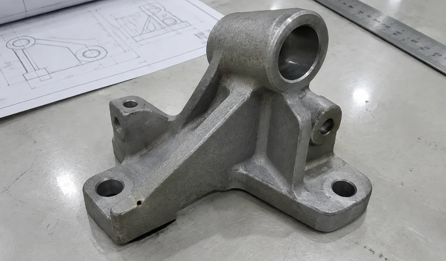
The short answer is no, not all indications are grounds for rejection. The acceptability of any potential investment casting defect depends entirely on its type, size, and location relative to the part's functional requirements.[1] A small gas pore on a non-critical surface of a bracket is a completely different issue from the same indication on a high-pressure valve seat. Judgment requires context, which a photograph alone rarely provides.
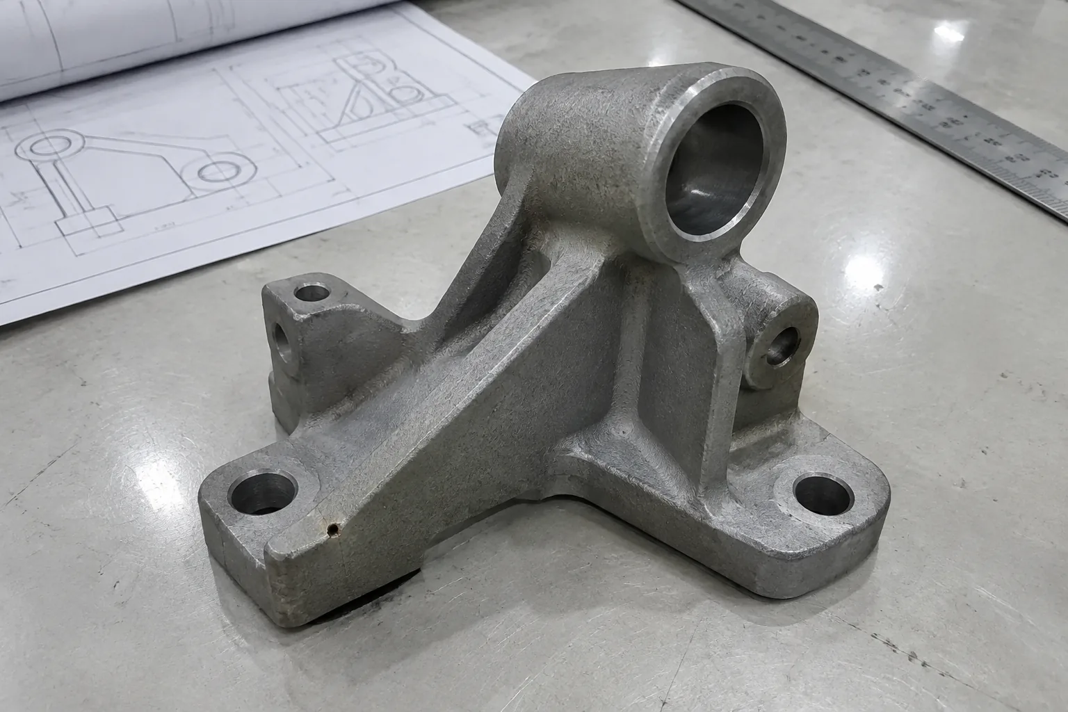
Understanding the difference between a cosmetic flaw and a critical failure is the key to managing quality without derailing your project. This guide will walk you through the practical decision-making framework we use with our customers to evaluate parts, establish clear standards, and ensure the components you receive meet your true engineering requirements.
How Do You Decide if an Indication is a Defect?
The most common source of friction between a buyer and a foundry isn't a part that is obviously scrap. It's a part with a visible indication in a gray area, where acceptance criteria were never clearly defined. A productive decision requires a structured approach.
Before you can judge a part, you need to answer a few fundamental questions. Without this information, any decision to accept or reject is based on guesswork, not engineering.
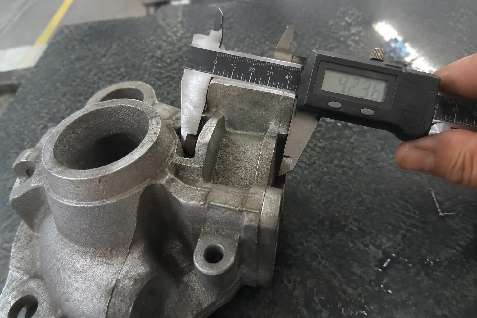
In my experience, the conversation becomes much clearer once we move past a simple "is this okay?" and start asking more specific questions. Let's break down the essential framework for evaluating potential investment casting defects.
H3: Where is the Defect Located?
Location is everything. The first step is to pinpoint the indication on the engineering drawing. Is it on a non-functional, as-cast surface? Or is it located on:
- A sealing face or O-ring groove
- A load-bearing section or structural rib
- A high-stress area, like a sharp corner or fillet
- A surface that will be machined later
- A bore for a bearing or press-fit component
A mark on a cosmetic surface carries a much lower risk than the same mark on a functional surface. A marked-up drawing showing the exact location is the single most important piece of information you can have.
H3: What Do Your Drawings and Specs Say?
The second filter is the documentation. Your purchase order, engineering drawing, and any referenced quality documents are the contract.
- Does the drawing call out specific acceptance standards (e.g., ASTM, ISO, MSS-SP-55)?
- Is there a specific surface finish requirement for that area?
- Was a visual acceptance standard established using a "golden sample" from the first article inspection?
If no standard was agreed upon before production, you and your supplier are trying to solve a problem without a shared rulebook. This is why we push to clarify these requirements during the initial quote and drawing review, long before any metal is poured.
H3: How Was the Defect Detected?
The inspection method determines what you can and cannot conclude.
- Visual Inspection: Confirms something is visible on the surface. It tells you nothing about depth or subsurface integrity.[2]
- Dye Penetrant Testing (PT): Reveals surface-breaking cracks, cold shuts, and porosity that might be too small to see visually.[3]
- Radiographic Testing (RT or X-ray): Shows internal voids, shrinkage, and inclusions. This is essential for confirming the internal soundness of critical sections.
- Ultrasonic Testing (UT): Can detect subsurface flaws and measure wall thickness.[4]
Rejecting a part for a potential internal flaw based only on a visual surface check is a premature decision. The detection method must match the risk you are trying to mitigate.
Is Porosity Always an Investment Casting Defect?
You've just unpacked a casting and see a tiny pinhole on the surface. Is the whole batch bad? The temptation is to demand parts with zero visible porosity, but this is rarely a practical or necessary standard.
The answer is that porosity is only a critical defect when it compromises the part's function. For many applications, small, isolated surface porosity in non-functional areas is perfectly acceptable and falls within industry standards.
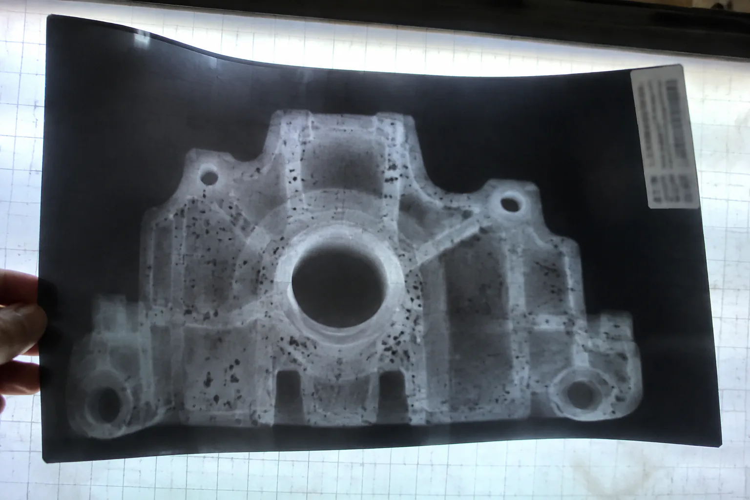
Porosity refers to small voids in the metal, typically formed by trapped gas or by dissolved gases that are released as the metal solidifies.[5] A related issue, shrinkage, occurs when a section of the casting cools and solidifies without enough liquid metal to feed it, creating a cavity. From a buyer's perspective, both are voids, and the question is the same: does this void matter?
The most common disagreement I see isn't about a part riddled with holes. It's about a casting with minor surface porosity in a non-critical zone, where the buyer and supplier never agreed on an acceptance standard. The buyer defaults to a mental rule of "no visible porosity," which is not achievable for most commercial investment castings[6] and is stricter than what industry standards like MSS-SP-55 (for valves) or other ASTM references require.
Here’s a more productive way to think about it:
- Location: A pore on a decorative logo is irrelevant. A pore on a surface that must hold pressure or seal against a gasket is a reason to hold the part for further evaluation.
- Machining: If a surface with porosity is going to be machined away, the porosity in the raw casting is not a defect in the finished part. The key is ensuring enough machining stock was included in the casting design to clean up the surface.
- Specification: For pressure-retaining parts like pump housings or valve bodies, the drawing should specify the level of radiographic or dye-penetrant inspection required to ensure the part is sound.
Before rejecting a part for porosity, confirm its location relative to the drawing, its depth (if possible), and what your agreed-upon acceptance standard permits.
What's the Difference Between Cold Shuts and Flow Lines?
You see a fine line on the surface of your casting. It could be a harmless surface pattern, or it could be a crack-like flaw that compromises the entire part. Confusing a flow line with a cold shut is a common mistake that leads to both over-rejection and under-rejection.
A cold shut is a true defect, while a flow line is usually cosmetic. A cold shut is a linear discontinuity where two streams of molten metal met but failed to fuse completely, often because they cooled too much. This creates a seam that can act as a crack and is a serious structural concern, especially in load-bearing or pressure-retaining parts.
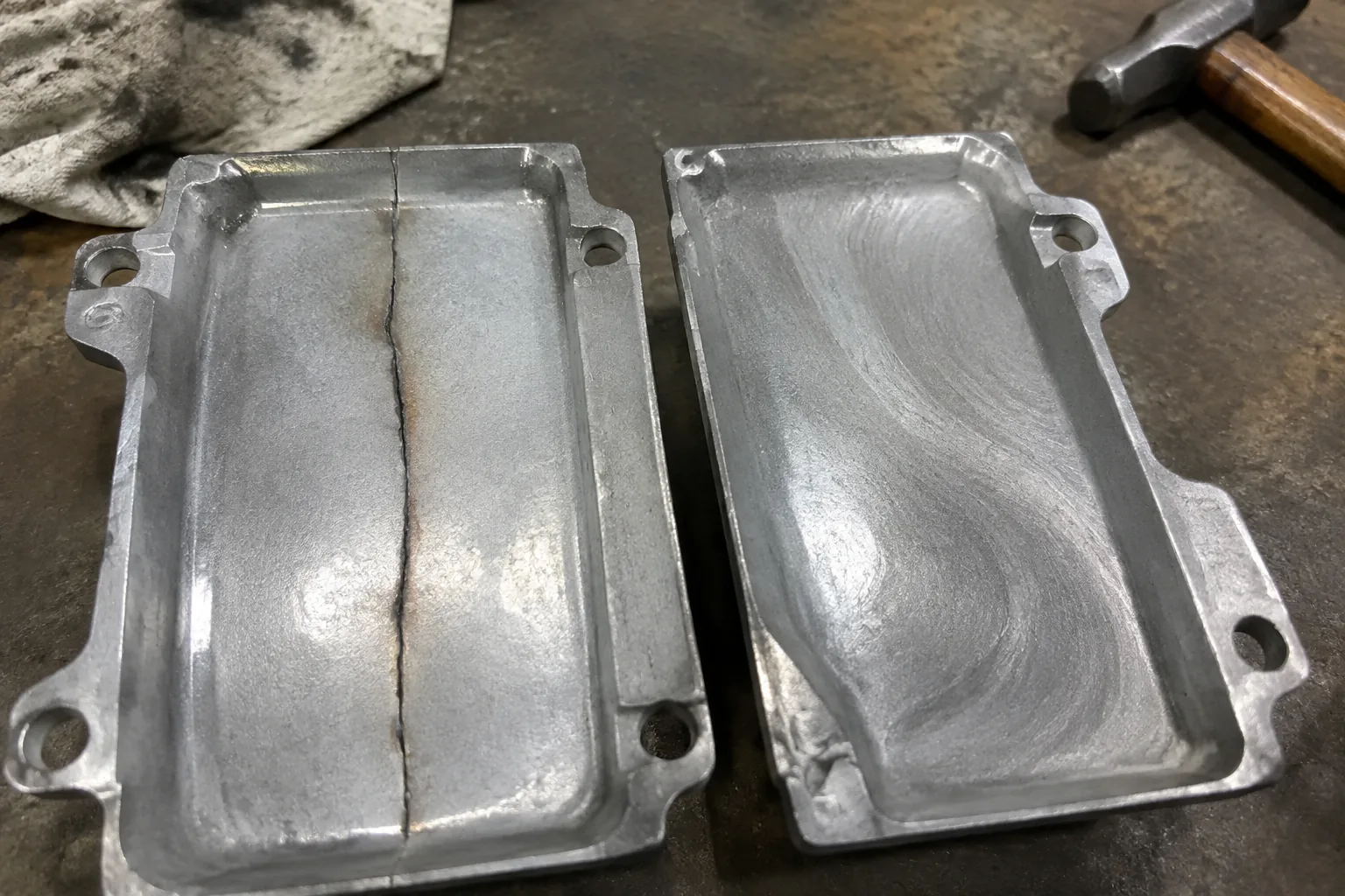
A flow line, on the other hand, is simply a visible trace on the surface that shows how the metal flowed into the mold. It might look like a faint pattern or swirl. Flow lines are typically very shallow and do not represent a lack of fusion. On non-critical surfaces, they are almost always acceptable.
The problem is that in a photograph, they can sometimes look similar. This is one of the main reasons we caution against making final acceptance decisions from photos alone.
Here’s a breakdown of the practical difference:
| Feature | Cold Shut | Flow Line |
|---|---|---|
| Nature | Lack of fusion between metal fronts | Surface pattern from metal flow |
| Appearance | Sharp, crack-like line | Faint, smooth, swirling pattern |
| Depth | Can penetrate into the part wall | Very shallow, surface only |
| Risk | Structural integrity risk | Typically cosmetic |
| Detection | Often confirmed with Dye Penetrant Testing | Visible to the naked eye |
When you see a linear indication, the first step is to establish which it is. This may require a simple dye-penetrant test at your facility or by the supplier. A cold shut in a critical area is a valid reason to reject the part or hold it for rework evaluation. A flow line on an external housing, however, is likely not a functional investment casting defect at all.
Why Does My Near-Net-Shape Casting Still Need Machining?
One of the great advantages of investment casting is its ability to produce complex parts with excellent dimensional accuracy and surface finish, often described as "near-net-shape." This reduces machining time and material waste. However, a common misunderstanding is that near-net-shape means no machining is required.
In reality, near-net-shape means less machining is required. Critical features like sealing faces, bearing bores, threads, and surfaces with tight tolerances (e.g., +/- 0.05 mm) almost always require a finishing machining operation. This is not a defect; it is a standard part of the manufacturing process plan.
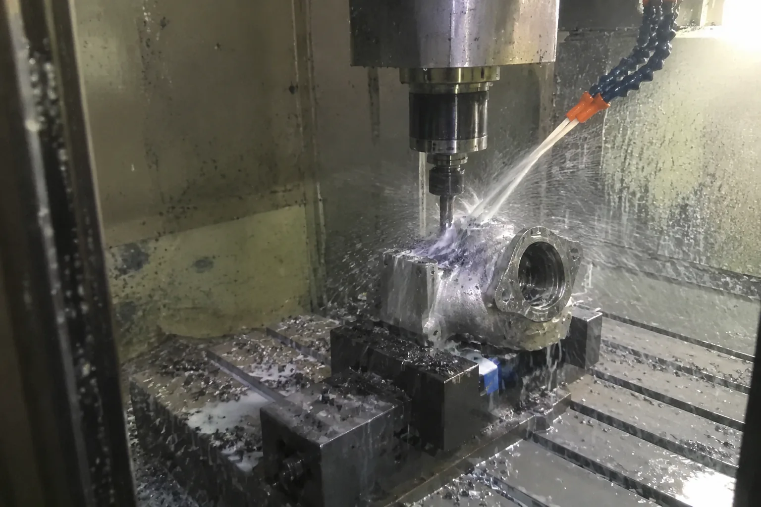
This misunderstanding creates problems when a buyer receives a raw casting and finds that a specific feature is not at its final tolerance. The reaction might be to claim a dimensional defect. However, the real question is whether that surface was ever intended to be used "as-cast."
For example, a typical investment casting process can hold a general tolerance of around +/- 0.1 mm per 25 mm[7], but this can vary with the size and complexity of the part. If your drawing requires a bearing bore to have a tolerance of H7, that cannot be achieved by casting alone. The raw casting will be designed with extra material (machining stock) in that area, which is then removed by CNC machining to achieve the final, precise dimension.
To avoid this conflict, the process needs to be clear from the start:
- Drawing Review: During our quoting process, we review the drawing with you to identify all features that require post-cast machining.
- Process Plan: We create a plan that clearly separates "as-cast" dimensions from "final-machined" dimensions.
- First Article Inspection (FAI): The FAI report will show dimensions for both the raw casting and the final machined part, so you can approve the entire process, not just one step.
If your drawing doesn't specify which surfaces are to be machined, there is room for misinterpretation. The time to align on this is before the tooling is made, not when parts arrive at your dock.
What Are the Practical Outcomes for a Casting with a Defect?
Once you have all the information—location, specification, and detection method—you can make an informed decision. Most situations fall into one of four categories.
When a customer sends a photo of a potential issue, the temptation is to give a quick "yes" or "no." The responsible answer is almost always, "It depends." The outcome hinges on a logical evaluation of risk and requirement.
The decision on what to do with a non-conforming part isn't always straightforward. After a thorough review using the framework we've discussed, the path forward usually falls into one of these four outcomes.
| Outcome | When It Applies |
|---|---|
| Accept for Use | The indication is in a non-functional area, all drawing requirements are met, and any applicable standard is satisfied. The part is fit for purpose. |
| Accept with Additional Inspection | An indication is found near a functional zone using a surface method (like visual). The subsurface condition is unknown, so further testing (like X-ray) is needed to confirm integrity before acceptance. |
| Hold for Rework and Reinspection | The defect is in a repairable location (e.g., minor surface porosity), an approved rework procedure exists (like minor blending), and a reinspection can confirm the repair was successful. |
| Reject and Recast | The defect affects structural or sealing integrity, rework cannot restore the required properties, the flaw is in a non-repairable area, or the cost of rework/re-inspection exceeds the part value. |
It's important to note that rework is not a universal solution. For example, weld repairs on certain steel alloys are highly controlled procedures. They often require specific welder qualifications, a qualified welding procedure (WPS), post-weld heat treatment to restore material properties, and full re-inspection of the repaired area.
Simply grinding down a surface blemish might be acceptable in one case, but for a critical part, you need to ensure the rework doesn't introduce new problems. A supplier who can explain the cause, propose a clear rework and inspection plan, and document the results is a partner. One who cannot is a risk.
Frequently Asked Questions
Do investment castings need to meet a specific porosity standard?
This depends entirely on the part's application and the purchase agreement. There is no single, universal porosity standard. Industry references like ASTM E155 for radiographic standards exist, but the buyer must specify the applicable acceptance level in the purchase order. Without a specified standard, there is no shared basis for judgment.
If a defect is only visible after machining, who is responsible?
Responsibility depends on the requirements agreed upon at the quoting stage. If a surface was required to be defect-free after machining (e.g., a seal face), this should have been specified on the drawing. If machining exposes subsurface porosity that was not detectable in the raw casting, the buyer and foundry must review the original process plan and inspection criteria to determine the path forward.
Can surface porosity be repaired by impregnation?
Vacuum impregnation is a process used to seal porosity in castings to ensure pressure tightness. It can be an acceptable solution if approved by the buyer's engineering team and permitted by the relevant specification. However, it is not a fix for structural defects like shrinkage cavities or cold shuts and should always be agreed upon in advance.
How do I establish an acceptance standard before production starts?
The best way is during the First Article Inspection (FAI) process. Request a full dimensional report, material certification, and detailed photos of the sample part. For critical parts, agree on specific non-destructive testing (NDT) requirements and use the approved first article as the "golden sample" or visual standard for mass production.
Conclusion
Not all visible marks are critical investment casting defects, and enforcing a "zero visible defects" standard is often impractical and unnecessary. The most important question is always whether a specific indication, in its specific location, prevents the part from meeting its engineering and functional requirements as defined on the drawing.
Answering this question productively requires a partnership between the buyer and the foundry, built on clear communication. This starts with a detailed drawing, an agreed-upon acceptance standard, and an inspection method appropriate for the part's application. In our experience, most disputes over quality trace back to a missing piece in this foundation, not a fundamental disagreement about what makes a good part. Establishing this basis before production is always more efficient than arguing about it after.
Ready to partner with a supplier who prioritizes clear process planning and technical communication? Send us your drawing or project requirements. Let's work together to define the right quality standards for your parts from day one.
Sources & references
Reference note
A casting inspection standard or foundry engineering reference should be cited to show that discontinuity acceptance is normally evaluated against specified criteria such as type, extent, and location rather than by visual presence alone. Evidence role: general_support; source type: institution. Supports: Acceptance criteria for casting discontinuities are based on specified standards and the relevance of the indication to the component's service function.. Scope note: Such sources generally describe inspection principles and standards-based evaluation; they may not prove acceptability for any individual part without its drawing and service conditions.
Reference note
An NDT educational reference should be cited to support that visual inspection is a surface examination method and cannot, by itself, establish the depth of an indication or the presence of subsurface defects. Evidence role: mechanism; source type: education. Supports: Visual testing is limited to surface-observable features and does not characterize internal discontinuities..
Reference note
An NDT reference should be cited to support that liquid penetrant testing is intended for detecting surface-breaking discontinuities, including fine cracks and open porosity that may be difficult to see visually. Evidence role: mechanism; source type: education. Supports: Liquid penetrant testing detects surface-breaking discontinuities through capillary action and visual indication after developer application..
Reference note
An NDT reference should be cited to support that ultrasonic testing can be used both for subsurface flaw detection and for thickness measurement in metallic parts. Evidence role: mechanism; source type: education. Supports: Ultrasonic testing uses high-frequency sound waves to identify internal flaws and measure material thickness..
Reference note
A materials engineering reference should be cited to support the definition of casting porosity as voids in metal that can arise from gas entrapment or dissolved gases released during solidification. Evidence role: definition; source type: education. Supports: Gas porosity in cast metals is associated with entrapped gas or gas evolution during solidification..
Reference note
A recognized casting inspection standard should be cited to show that commercial casting evaluation commonly uses graded acceptance levels for porosity and other discontinuities rather than a universal zero-visible-defect requirement. Evidence role: expert_consensus; source type: institution. Supports: Casting acceptance standards often classify and permit limited surface or internal discontinuities rather than requiring absolute absence of porosity.. Scope note: This supports the general industry context; acceptability for a specific casting still depends on the contract, drawing, material, and service conditions.
Reference note
A published investment-casting tolerance standard or engineering handbook should be cited to substantiate the approximate tolerance of ±0.1 mm per 25 mm as a typical process capability range. Evidence role: statistic; source type: institution. Supports: Published investment-casting tolerance guidance provides typical dimensional tolerance ranges comparable to the article's stated value.. Scope note: The cited value should be treated as a general guideline, not a guaranteed tolerance for every alloy, geometry, foundry, or inspection condition.