
Design for Manufacturing · engineering brief
Investment Casting Wall Thickness Guide: How Thin Is Too Thin?
Feasible investment casting wall thickness depends on alloy, flow length, geometry, section transitions and process controls. Use DFM review before fixing tooling dimensions.
01There is no universal minimum wall thickness for every alloy and geometry.
02Uniform transitions and feed paths matter as much as the nominal section value.
03Simulation and sample validation reduce risk but do not guarantee production yield.
On this page
- Why is investment casting wall thickness critical for your tooling investment?
- What is the actual minimum investment casting wall thickness?
- Does reducing investment casting wall thickness actually save production costs?
- How can DFM analysis validate your investment casting wall thickness before tooling?
- Frequently Asked Questions
- Conclusion
Guessing the correct investment casting wall thickness can completely derail your manufacturing project before production even begins. If you misjudge these dimensions, you risk scrapping expensive molds, facing endless delays, and throwing away your budget on failed casting trials. Mastering these dimensional limits is the only way to lock in the right manufacturing process early and guarantee a flawless production run.
Investment casting wall thickness is the structural foundation of your metal part, dictating molten metal fluidity, cooling rates, and overall manufacturability. While generic industry guidelines suggest a minimum of 3mm (0.12 inches), the true safe limit depends entirely on your specific 3D geometry, material choice, and part size. Ignoring these variables often leads to catastrophic tooling failures.
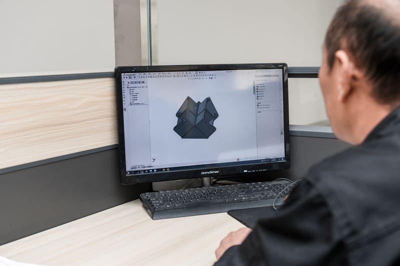
You might think saving a few millimeters of metal will drastically cut your unit costs, but the manufacturing reality is much more complex. Let me walk you through the hidden risks of wall dimensions and how to avoid the expensive tooling mistakes I see procurement teams make every year.
Why is investment casting wall thickness critical for your tooling investment?
Procurement managers often trust their initial CAD design specs without questioning actual castability. But when a supplier blindly accepts those aggressive dimensions, you are walking into a financial trap. A single miscalculation here can force you to abandon your chosen manufacturing process entirely.
Investment casting wall thickness directly dictates whether molten metal can successfully fill the ceramic mold before solidifying.[1] If the designed walls are too thin for your chosen alloy, you will face severe misruns and warping. This error forces companies to scrap their initial molds, rework their designs, and pay for entirely new tooling.
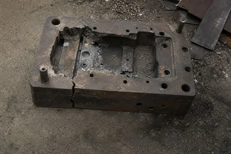
The Tooling Rework Trap: A Real-World Disaster
I still remember a desperate call I took from a sourcing engineer late last year. His company had designed a complex stainless steel industrial pump housing. To reduce the overall weight of the final assembly, the product developers aggressively thinned out the internal walls. They misjudged the required investment casting wall thickness and pushed their previous supplier for an ultra-thin design.
The previous supplier simply wanted the order. They accepted the 3D model without conducting a proper Design for Manufacturability (DFM) review and immediately cut the aluminum molds for the wax patterns.
When the first-article casting trials began, the molten stainless steel cooled much too fast inside the thin cavities. The result was a total disaster. The parts suffered from severe misruns—meaning the metal simply did not reach the end of the mold—and structural warping. Because the walls were fundamentally too thin for investment casting, they considered switching to an entirely different, less suitable manufacturing process.
Ultimately, the initial mold and all the preparation work were completely ruined. They had to scrap the first attempt entirely. When they came to us to rescue the project, we had to add material back into the 3D model, invest in entirely new tooling, and run new trials just to meet their original functional standard. That single dimensional misjudgment wasted four months of time and thousands of dollars in tooling costs. Wall thickness is never just a dimension on a drawing; it is a critical process parameter that dictates your project's survival.
What is the actual minimum investment casting wall thickness?
Are you searching for a universal chart that tells you exactly how thin you can cast a metal part? Relying on standard marketing brochures for these numbers is incredibly dangerous. What works perfectly for a simple, flat bracket will absolutely fail on a complex, multi-layered housing.
There is no single minimum investment casting wall thickness that applies to every project.[2] While many generic supplier brochures claim 2mm to 3mm as a baseline, the actual limit depends heavily on the part's overall size, geometric complexity, and the specific alloy's fluidity. You cannot determine a safe minimum without evaluating the specific 3D model.
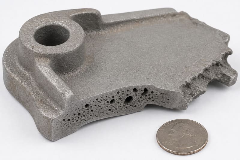
Dispelling the Minimum Thickness Myth
Whenever a product developer asks me, "How thin can you cast?", I always reply with a request: "Send me your 3D STEP file first." Asking for an absolute minimum without providing geometric context is the wrong approach to custom metal manufacturing.
Three primary variables dictate how thin your walls can actually be:
- Alloy Fluidity: Different metals behave differently when melted. For example, aluminum alloys generally have excellent flow characteristics, allowing them to fill thinner sections.[3] High-carbon steels or specific stainless steels cool rapidly and become sluggish, requiring thicker walls to prevent freezing mid-pour.
- Flow Length (Part Size): Molten metal constantly loses heat as it travels through the cold ceramic shell.[4] A 2mm wall might cast perfectly if the molten metal only needs to travel 10mm. However, if that same 2mm wall extends for 150mm, the metal will freeze prematurely.
- Geometric Transitions: Sharp corners, deep pockets, and abrupt changes from thick to thin sections cause turbulence.[5] This turbulence traps air and slows down the metal flow.
Contextual Baselines for Common Alloys
While I strongly advise against trusting absolute numbers blindly, the table below illustrates how different materials generally behave under optimal, simplified conditions. Notice how the limiting factors change based on the material.
| Alloy Material | General Realistic Baseline | Key Limiting Factor for Thin Walls |
|---|---|---|
| Aluminum Alloys | 2.0mm – 3.0mm | Prone to trapped gas if flow is too turbulent. |
| Carbon Steel | 3.0mm – 4.0mm | Rapid cooling reduces fluidity over long distances. |
| Stainless Steel (304/316) | 3.0mm – 4.5mm [6] | High risk of shrinkage porosity in isolated thin sections. |
| Brass / Bronze | 2.5mm – 3.5mm | Requires careful gating to maintain consistent temperature. |
Do not treat these numbers as a guarantee. Your specific design geometry might require a 5mm wall even if you are using aluminum, simply because of the flow path length.
Does reducing investment casting wall thickness actually save production costs?
It seems entirely logical at first glance: thinner walls mean less raw material usage, which should naturally lead to lower unit costs, right? Unfortunately, aggressively thinning out your metal design to save pennies on steel often explodes your total cost of ownership.
Designing an overly thin investment casting wall thickness rarely saves money in the long run. Thinner walls drastically increase the risk of misruns, shrinkage porosity, and warping during the cooling phase.[7] This spikes the manufacturing scrap rate, drives up quality control costs, and often leads to expensive tooling rework.
The Cost vs. Defect Risk Trade-off
I often sit down with procurement teams who are frustrated by rising costs. They try to shave 100 grams of steel off a casting to save a few cents per unit. But in custom metal manufacturing, material weight is only one fraction of the total price. When you push the physical limits of a casting process, you introduce severe defect risks.
If reducing the wall thickness increases your supplier's scrap rate from a healthy 2% to a disastrous 25%, the supplier will eventually bake those losses into your unit price. Worse, defective parts might slip through quality control, causing catastrophic failures in your final assembly.
Here are the specific defects triggered by overly thin walls:
- Misruns (Incomplete Fill): As the molten metal navigates a very thin cavity, it loses heat rapidly to the ceramic mold. If it freezes before filling the entire cavity, the part comes out incomplete.
- Shrinkage Porosity: Metal shrinks as it cools and solidifies. If a thin wall separates a thick section from the metal feed (the gate), the thin wall will freeze first.[8] This cuts off the molten metal supply to the thick section, leaving internal voids or sponge-like holes known as shrinkage porosity.
- Warping and Distortion: Thin sections cool significantly faster than adjacent thick sections. This uneven cooling creates massive residual internal stresses.[9] Once the part is removed from the mold, these stresses cause the part to bend, warp, and pull completely out of your tight dimensional tolerances.
In my experience rescuing troubled projects, we often recommend adding a small amount of material to certain areas. A slightly thicker, uniform wall ensures a smooth, stable casting process. A stable process reduces scrap, eliminates the need for constant rework, and ultimately reduces the actual cost per good part delivered to your warehouse.
How can DFM analysis validate your investment casting wall thickness before tooling?
Many buyers eagerly hand over their CAD files, negotiate a quote, and immediately authorize mold production to save time. But what happens if the supplier never actually verified the manufacturability of the design? You end up paying for their painful learning curve.
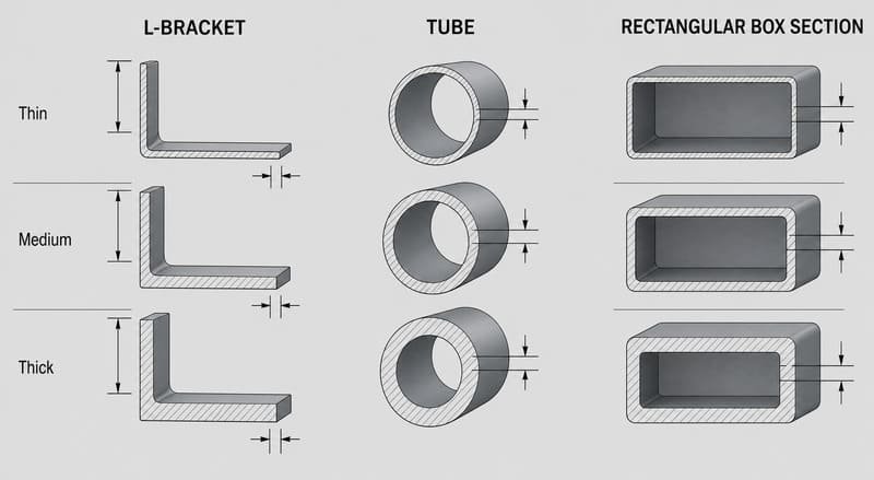
You must demand a Design for Manufacturability (DFM) analysis to validate your investment casting wall thickness. A robust DFM report evaluates your specific 3D model for metal flow, cooling rates, and potential defect zones. This ensures the design is genuinely castable before a single dollar is spent on expensive tooling.
Evaluating Suppliers Through Engineering Support
A reliable custom metal manufacturing partner will never just say "yes" to win your purchase order. They will challenge your design if they see risk. When our engineering team receives a 3D model from a new client, we immediately run it through comprehensive DFM checks. If we spot a 2mm wall stretching across a 200mm long stainless steel bracket, we will flag it immediately.
Instead of taking a supplier's "ultra-thin casting capabilities" as absolute fact, you should use the DFM process to verify their competence. A proper DFM review for wall thickness should include:
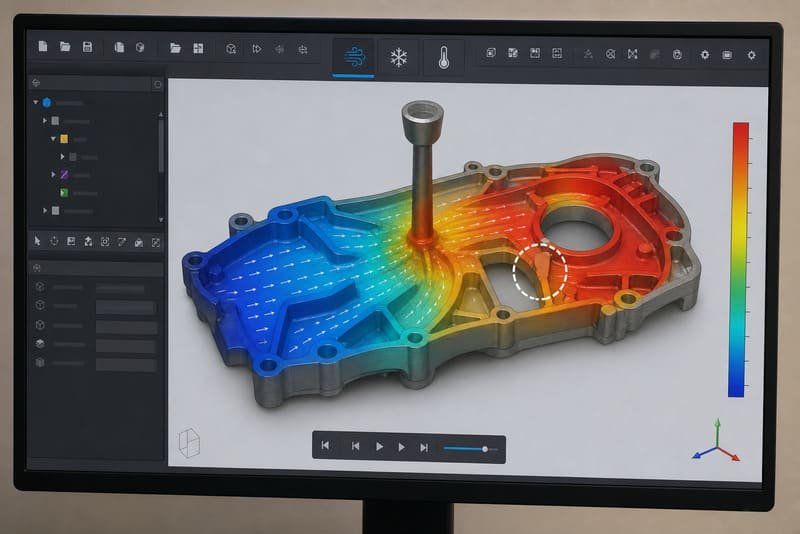
- Mold Flow Simulation: Advanced software simulates how the molten alloy enters the ceramic shell.[10] It highlights cold shuts, turbulence, and areas where the metal will likely freeze before filling.
- Thermal Cooling Analysis: The review must identify isolated hot spots. It ensures that the gating system can adequately feed molten metal through the thinner walls to the thicker sections during the cooling phase.
- Transition Optimization: The engineer should recommend adding fillets, radii, or gradual tapers to any sharp corners where thick walls meet thin walls.
Before you cut any molds, ask your potential supplier these specific questions:
- "Have you simulated the metal flow for these specific thin sections in my model?"
- "Where do you anticipate shrinkage porosity based on my current wall transitions?"
- "If the initial trial shows warping due to uneven cooling, what is your contingency plan?"
If the supplier cannot answer these questions confidently, they do not understand the quality and tooling risks associated with your design. Do not risk your tooling budget on a guess.
Frequently Asked Questions
What is the standard tolerance for investment casting wall thickness?
Standard tolerances typically fall around ±0.13mm per 25mm (±0.005 inches per inch), depending on international standards like VDG P690.[11] However, if your assembly requires much tighter dimensional accuracy, we usually cast the wall slightly thicker and achieve the final dimension through secondary CNC machining.
Can I transition directly from a thick wall to a thin wall in a casting?
No, sudden transitions cause uneven cooling rates, which inevitably lead to shrinkage porosity, warping, and cracking. You should always use generous fillets and gradual tapers to ensure smooth metal flow and uniform cooling throughout the entire part.
How does material choice affect wall thickness capabilities?
Different metal alloys possess varying levels of fluidity when molten. For example, aluminum alloys generally flow much better than high-carbon steels. This higher fluidity allows aluminum to fill slightly thinner walls and more complex geometries without risking premature freezing and misruns.
Why not just use die casting for very thin walls?
Die casting forces molten metal into a steel mold under extreme pressure, making it ideal for extremely thin walls.[12] However, die casting requires much higher upfront tooling costs and is largely limited to non-ferrous metals like aluminum and zinc. Investment casting allows you to cast high-strength steel alloys without the massive mold investment.
Conclusion
Getting your investment casting wall thickness right is the critical difference between a smooth product launch and a complete tooling disaster. As we have seen, guessing these dimensions or relying on generic minimum thickness charts inevitably leads to high scrap rates, tooling rework, and wasted manufacturing budgets. You must balance the desire for lightweight parts with the practical reality of metal fluidity and cooling dynamics.
Always prioritize a thorough DFM analysis over hollow supplier promises. If you have a 3D model ready and want to ensure your design is truly manufacturable without risking your tooling budget, our engineering team is here to help. Reach out to us today for a comprehensive DFM evaluation, and let us be your reliable manufacturing partner from initial prototype to flawless volume production.
Engineering scope: Published thickness and tolerance ranges are general engineering references, not Tianluping production guarantees. Final feasibility depends on alloy, geometry, flow length, section transitions, tooling, gating and inspection requirements and must be confirmed against the controlled drawing.
References & technical sources
View source list12 sources
- Metal Casting — courses.washington.edu
- Casting — web.mit.edu
- Castability Control in Metal Casting via Fluidity Measures — web.wpi.edu
- 1. Investment casting heat transfer1 — dspace.mit.edu
- Fundamentals of Casting — mie.njit.edu
- Experimental Study of the Filling of Thin-Walled Investment ... — academia.edu
- Casting Defects Analysis in Foundry and Their Remedial ... — academia.edu
- Designing thin and thick sections is an ... — bdml.stanford.edu
- 3.7 Simulation of Distortions and Pattern Allowances for a ... — beckermann.lab.uiowa.edu
- Numerical Simulation Of Investment Casting Of Gold Jewelry — academia.edu
- DIMENSIONING METHODS OF INVESTMENT CASTING — cirexfoundry.com
- MSEC2013-1222 — tsapps.nist.gov